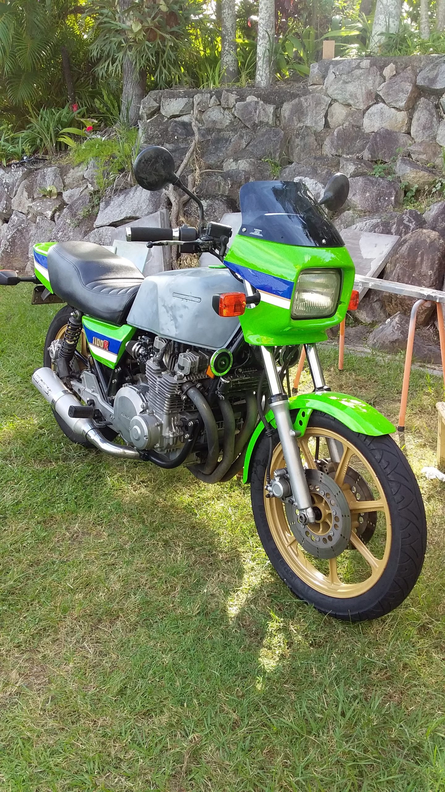
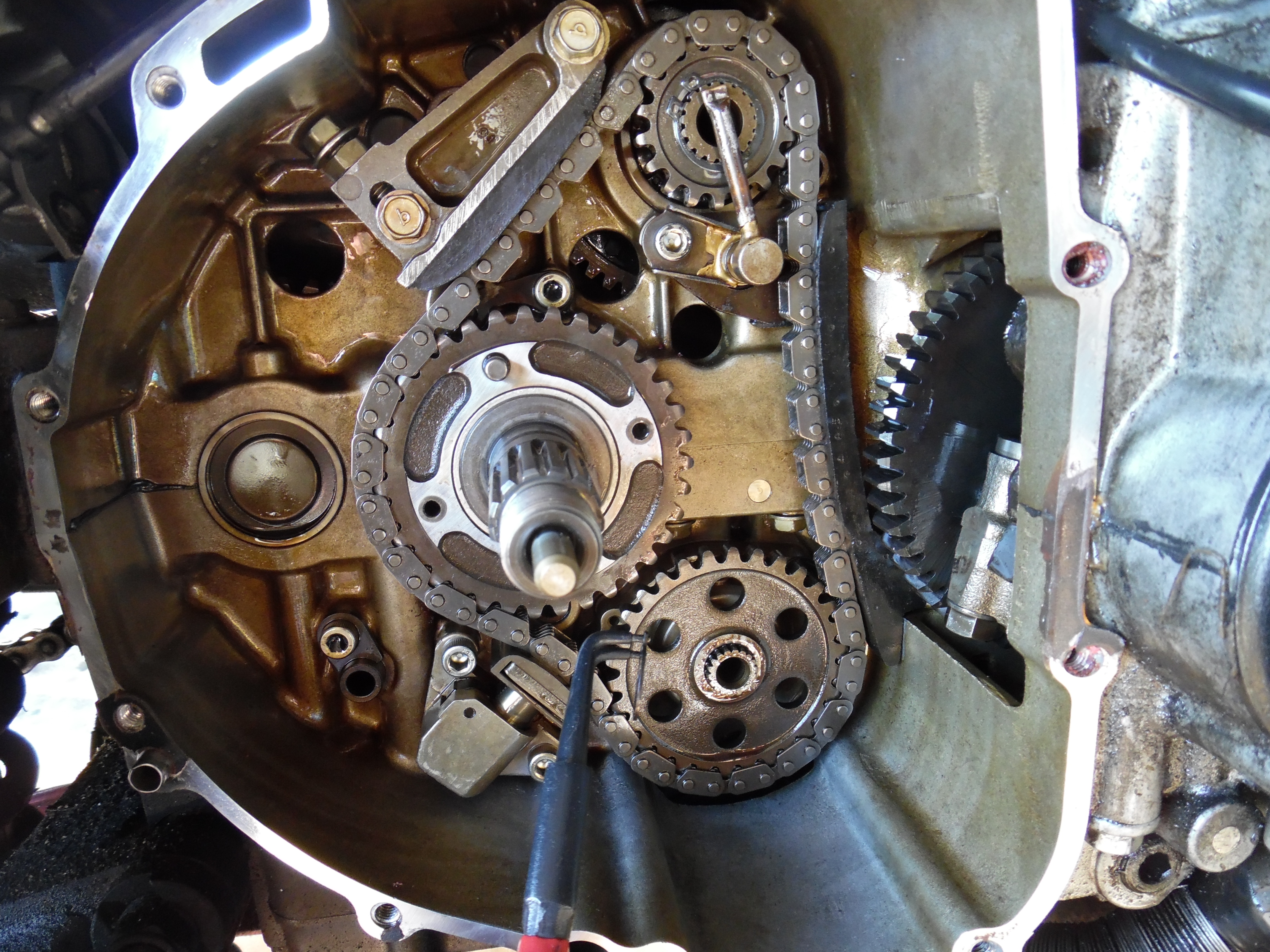
When production started in 1977 of the Kawasaki z650 B1 model, I doubt the Kawasaki engineers had any idea that 40 years later these bikes would still be on the road and highly sought after! But after a few decades various mechanical systems on the z650 start to show their age, the Starter Clutch is one and the Clutch cush drive (damper rubbers) is another.
The cush drive consists of 6 slotted dampening rubbers installed in the rear of the clutch basket that cushion the clutch during gear changes. It’s a sealed unit from the factory (sealed with machine pressed rivets) but can easily be replaced if given to a machine shop.
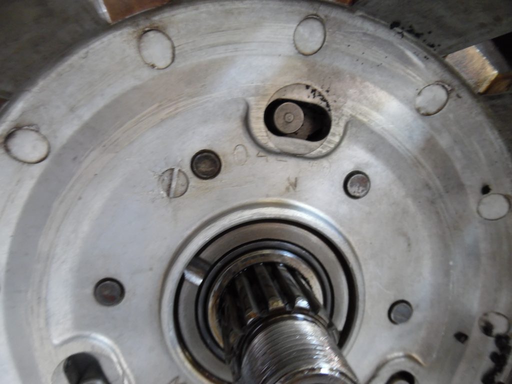
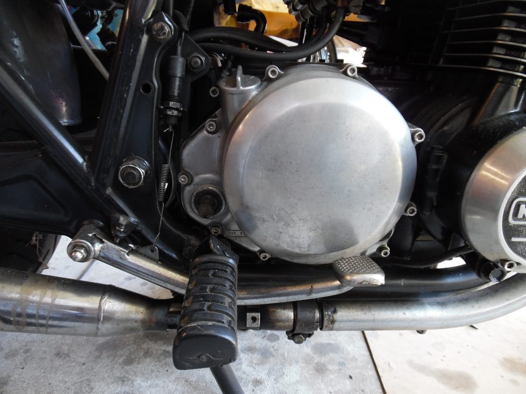
Worn Clutch cush drive rubbers can easily be checked with the clutch cover installed. When the clutch plates are removed a worn unit can easily be visually seen and diagnosed. in the picture below the cushioning unit’s locating pin is to the far left.
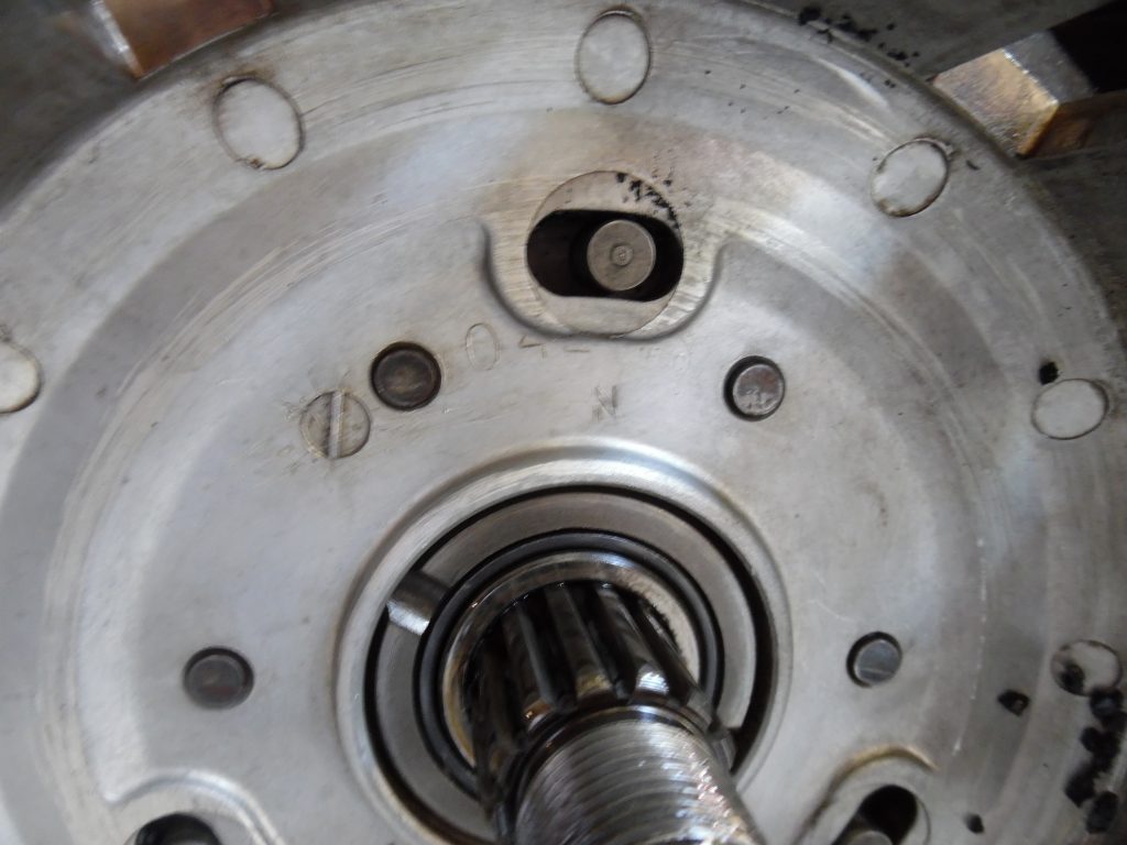
If the rubbers are worn then it is easy to move the clutch basket left and right as shown below.
Getting Started
Before you start removing anything, buy yourself a clutch cover gasket and have some 3M Threebond gasket goo on hand.
The clutch basket is easy to remove, first you need to remove the Kick Starter, Foot Peg and Foot Brake, then remove the screws that hold the Clutch cover.
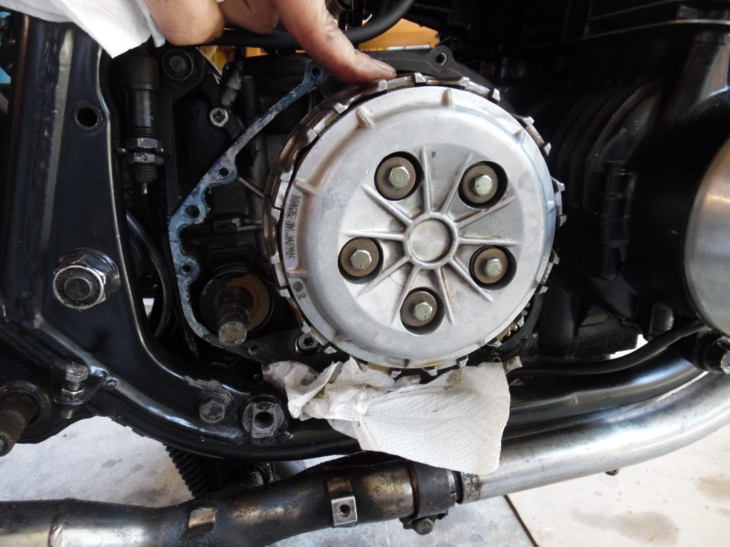
With the cover off, remove the 5 set screws that hold down the clutch pressure plate from the inner hub, this allows removal of the plates and then access to the nut that holds the Clutch Hub in place. The five set screws will need to be removed a few turns at a time so they are evenly removed. Make sure you have an oil drip pan or some kind of suitable container to catch any oil that drains out when the cover is removed.
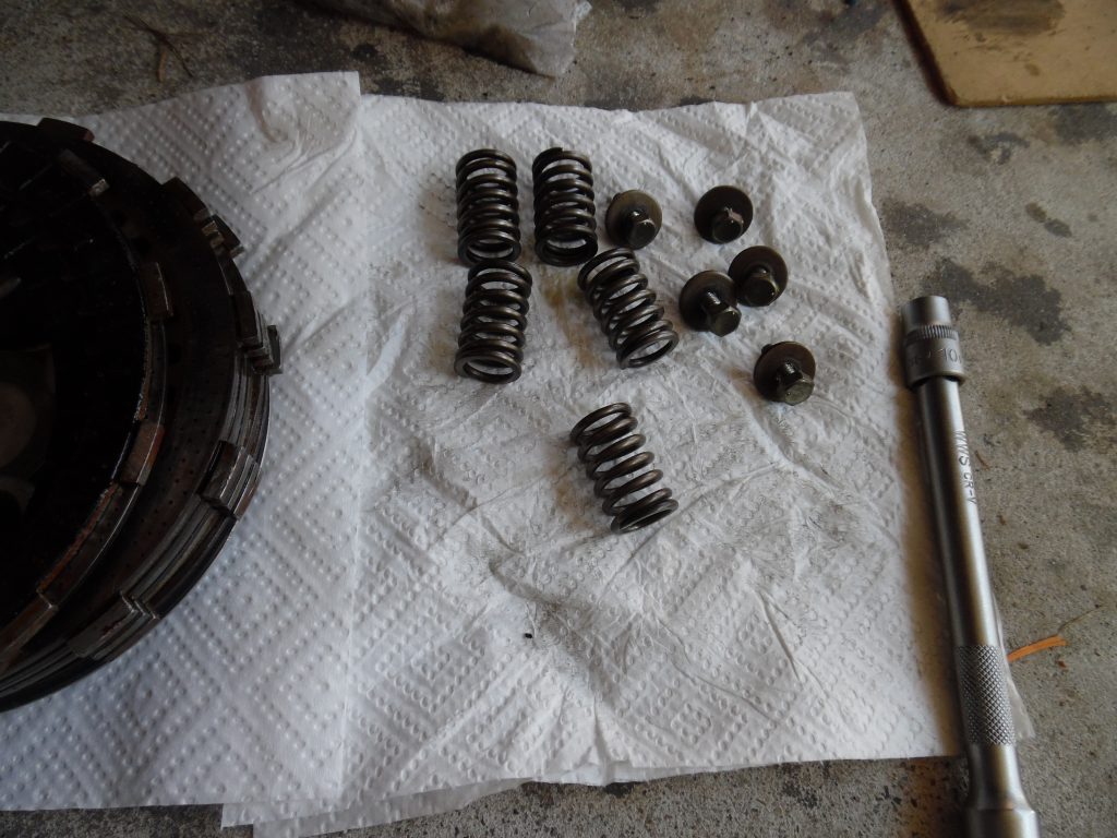
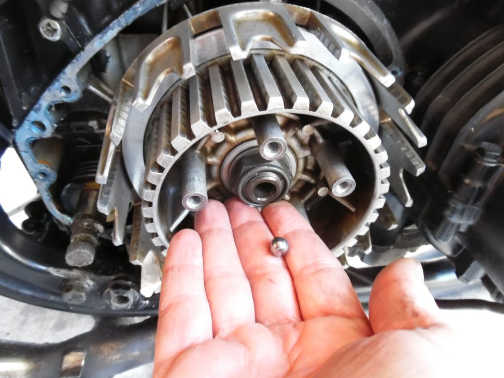
Once the pressure plate is removed (and the 7 clutch plates and 8 steel plates), you can access the clutch spring plate pusher piece and ball bearing. The rod that runs from the other side of the engine pushes against the ball bearing.
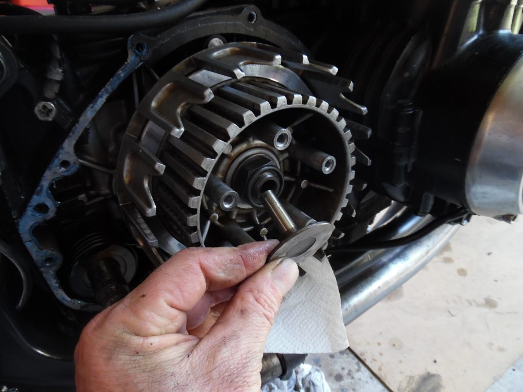
Use an air driven impact gun (A.K.A. rattle gun) and remove the nut, I suggest using a 6 sided impact socket of the exact size (should be 20mm). When you remove the nut, take note of the washer, it is installed one way only and should have “OUTSIDE” written on it.
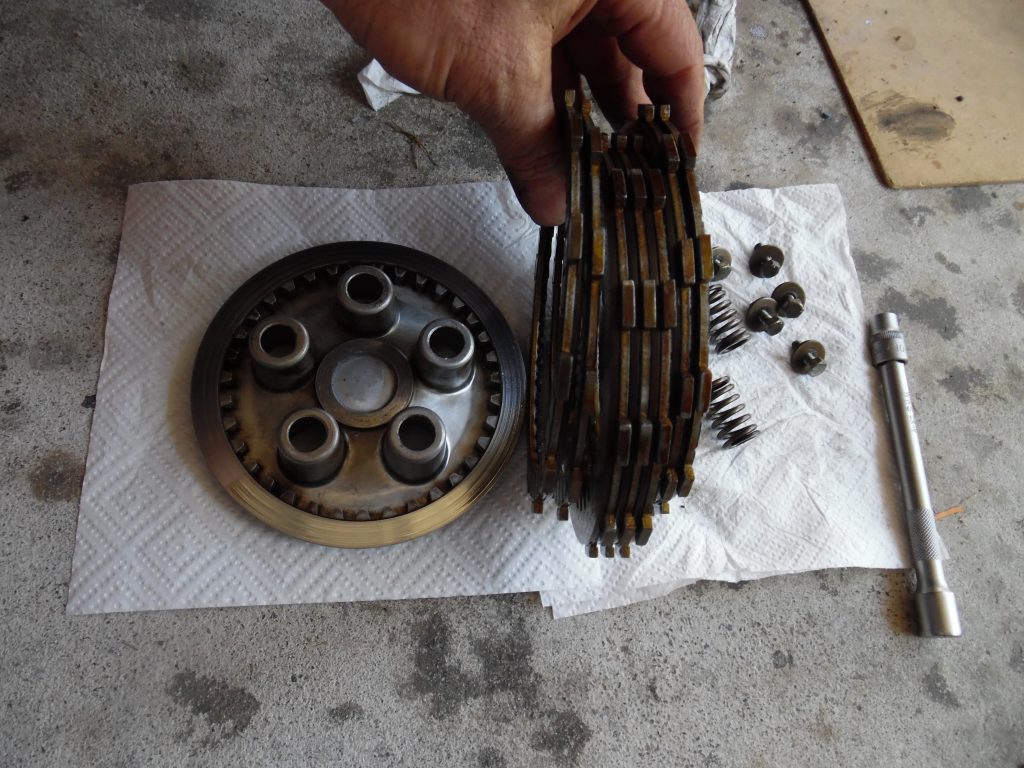
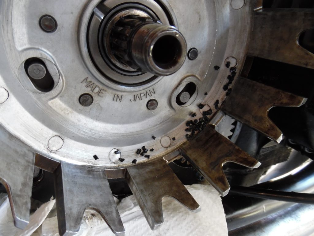
Once you have removed the clutch hub and bearing, check for tell tale signs that the cush drive rubbers are stuffed, usually there are small particles of the rubbers stuck to the basket. You can lift the basket out at this stage.
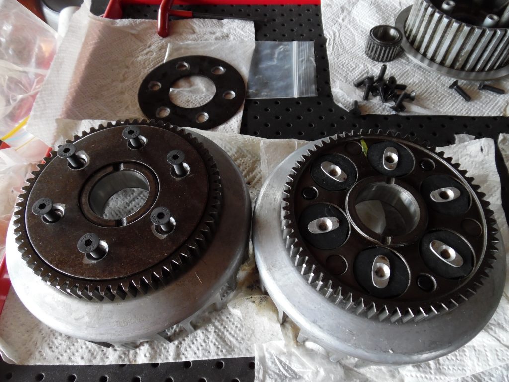
Remove the basket and meticulously clean up any trace of old rubber. When flipped upside down you can see the factory pressed rivets. For some reason I neglected to take a picture of the plate with factory rivets in place. So when you tip the basket over, you will see the plate riveted to the basket. Here is where the machine shop now comes to the rescue, they will machine out the heads of the rivets then drill out the rivets which are 5mm in diameter and then drill the alloy so you can install six M6 x 20mm length high tensile counter sunk set screws.
The machine shop will need to drill out the old pins and then drill, counter sink and tap the 5mm holes out to fit the 6mm set screws and counter sink the steel backing plate as well. Usually a 5mm drill hole allows a 6mm tap to be used.
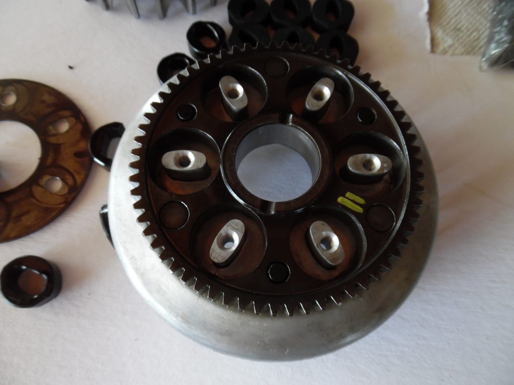
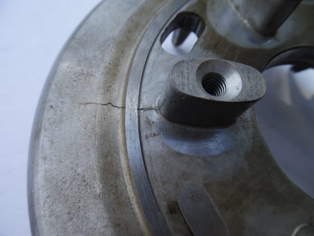
While your at it check for cracks. This hub has a crack but considering I’m not going to use it on the drag strip I think it will survive another 20 years with normal/gentle use.
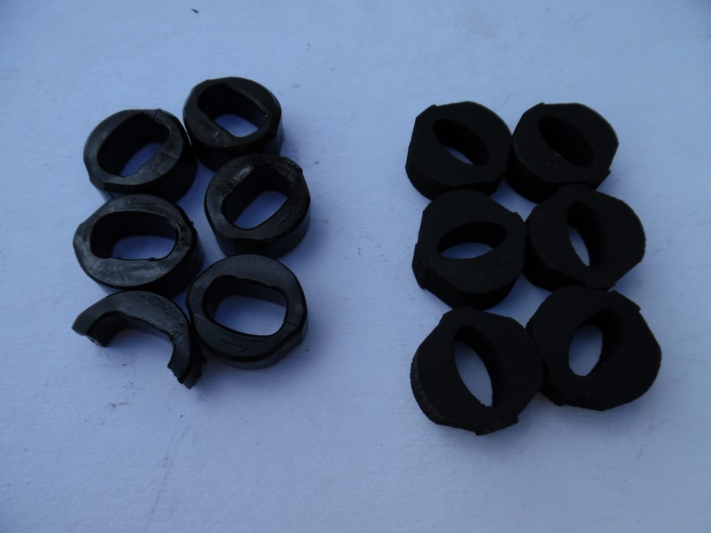
On the left are the original rubbers as removed, notice the inside hole is very large and one of them has split in half, the other half is shredded into a million small pieces. On the right is an after market rubber kit made of high quality oil and heat resistant rubber. I obtained two kits in a group buy on a z650 forum, one of the members had the kits laser cut.
Prior to torquing in the set screws, make sure you coat them in a thread locker, I bought a fresh bottle of Loctite 243 for this Job.

To complete the assembly process, install the rubbers, place the backing plate on top, install the set screws with thread locker, torque it down tight and the then basket is ready to re-install.
Final step is to assemble everything back:
- Fit the basket, then the hub.
- Install the washer the correct way round, hand install the nut then torque down to the correct setting as per your service manual
- Fit the ball bearing.
- Fit the friction and steel plates in the correct order after you have measured the thickness AND checked they are NOT warped.
- Install the pusher
- Fit the spring plate.
- Install the springs and secure down with the set screw and washer.
- Torque them down evenly.
- Make sure you meticulously clean the gasket surfaces so the alloy is free of old gasket on both the engine and cover. Use the 3M Liquid Gasket to seal both surfaces prior to installing the gasket and cover.
Your final task then is to fit the kick starter, foot peg and foot brake.
Start the engine and test out your new, smooth clutch 🙂