Motorcycle electrical system are generally considered a black art by most riders. Although fairly robust, when they do fail the charging and ignition systems present the most headache and generally rate at the top of most forum questions (next to “what oil should I use?”).
Types of Charging systems
Although I will focus on the z650B1 model in this article, I will produce a followup article on the rest of the z650 models as there appears to be 3 designs in use across the model line up. So if you have another model it will get covered. I also have an F1 and SR model in my collection so these will get special mentions in due course.
There are several ways to charge a motorcycle battery and for this article I will also use the terms Stator and Alternator to mean the same thing.
The first type of Alternator is a fixed magnet design where a magnet spins on the end of the crank and as it rotates, it generates an electric current in a three phase stator. The output of the stator usually goes to a 3 phase bridge rectifier and the output of that goes to the battery. The stator is also connected to a regulator that then clamps excess power to ground to stop the battery being overcharged. This basically means the stator is shorted out to stop it producing power when the battery is charged.
Although the B1 and C1 models dont use this design it is used in most of the later models.
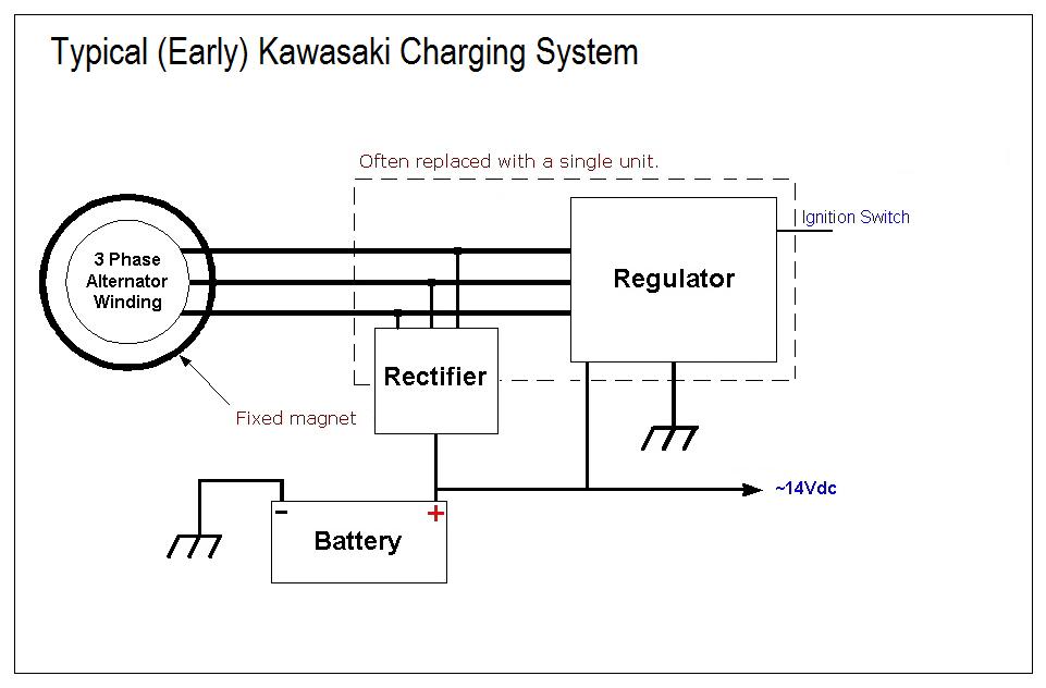
Why do this? Well you can in theory start the bike on a less than charged battery.
The second type of charging system is where the fixed magnet is replaced with a rotor that disrupts the magnetic field being generated by a field coil usually attached to the Altenator cover. Regulating the coil determines how much power the Alternator generates.
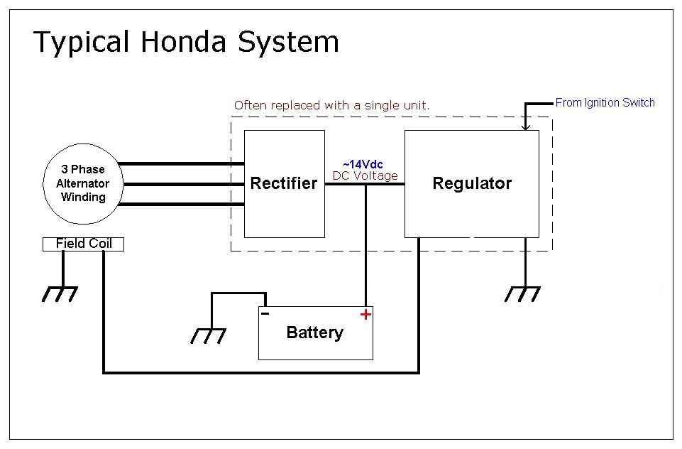
This has the advantage that the Alternator should last longer but the field coil will fail sooner. It also means you need a charged battery to start and run the engine.
Surprisingly the z650B1 model deviates away from the systems used on it’s bigger brothers, and shares a common design used in the Honda CB750, a field coil generating a controlled magnetic field.
Getting familiar…..
Below is the diagram for a Kawasaki 1977 z650B1, we will refer to it from now on.
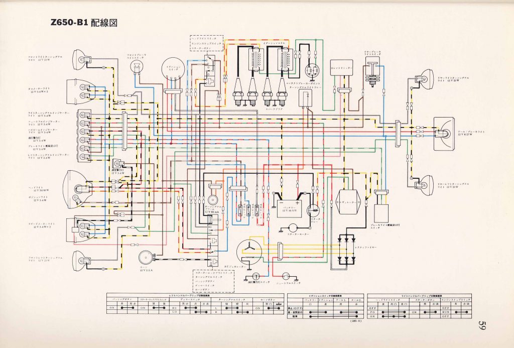
Looking at the diagram above you can see the three phase Stator, bottom middle, it has three (3) yellow wires coming from it to a three phase bridge rectifier. Thats the component with 6 diodes in it.
At the base of the Stator is the field coil, one side is earthed to the engine and the other is connected to the Regulator. One thing this does tell you is that you need a charged battery to start the engine.
The Regulator has three (3) connections to it. One is earth, one is connected to the battery and one goes to the ignition switch (and so it’s always connected to the battery).
Theory of operation
When you turn on your ignition the regulator gets powered so it checks the battery voltage and if the battery is below the float voltage, say 14.1 volts, it turns on the Field Coil.
Now depending on the type of regulator installed determines if the field coil is powered fully or its powered incrementally in proportion to the actual voltage needed and the voltage it detects from the battery. If you have an old CB750, then its just on and off thanks to a relay that switches the field coil.
As the engine spins the rotor disrupts the magnetic field causing a current to flow in the stator which generates a three phase Alternating Current. I wont elaborate on what this mean exactly, but it basically means that on a stator with three wires coming from it, AC voltage is produced on each of the three wires, so to test the stator, you need to measure the voltage between each pair (A-B, B-C and C-A) with the engine spinning and when stationary, measure the resistance between each pair to determine if there is a fault in the stator.
This current flows into the Rectifier and as the current flows through each diode in turn a Direct Current is formed and charges the battery.
The Regulator will detect the increase in battery voltage and then either turn off the Field Coil or throttle it back.
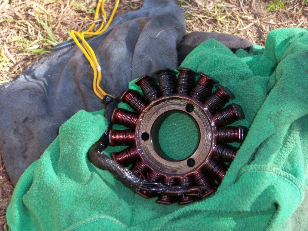
Now if you do not have a field coil then as your engine spins the regulator will instead short the field winding’s of the Stator to ground for a short time to reduce the output momentarily. The picture below shows a Stator which has been fried, in the process the integrated regulator/rectifier unit also failed.
Failures….
Battery Keeps going flat – Insufficient voltage to charge the battery is usually a failure in the stator but can be a regulator failure or open circuit diode. Start with the stator as it’s usually an open circuit on one or more windings. Disconnect it, start the engine and measure for AC voltage on each pair of windings. If one is dead, problem found, however the rectifier needs to be tested to ensure the cause is not a shorted diode. You also should suspect the regulator if the stator and diodes are OK. If you have an integrated unit then just replace it.
Testing the Field Coil – Since the z650 has a field coil, you need to check that it is being turned on, as its an electromagnet, it will attract ferrous metal when activated. Place a spanner next to it and see if you can feel it grabbing when the coil is enabled (its bolted to the Alternator cover). If not measure the coil’s resistance, you can also measure the voltage across the leads when the engine is running. No volts = no charge, 12volts+ means its turning on and hence the battery should charge. If its got voltage and not attracting metal, its burned out (do a resistance check to confirm).
Battery Over voltage – An over voltage condition will quickly destroy a battery and is usually a failure of the regulator. Basically the stator generates maximum voltage and the regulator has the field coil on hard resulting in the battery boiling out or just failing due to excessive voltage.
Summing Up
While the diagrams at the start of the article shows the three components separately (Stator, Rectifier and Regulator) the regulator and rectifier units can usually be replaced as a single unit in the event of failure for almost every model of motorcycle. When the stator fails its often better to replace all three components at the same time.
References
- https://en.m.wikipedia.org/wiki/Stator
- https://en.m.wikipedia.org/wiki/Rotor_(electric)